
Have you ever wished you had an instruction manual for your job? Imagine how nice it would be to have one sheet of paper with instructions and advice on how to do your job in the most efficient manner. Well, that’s what our engineers create for everyone on the shop floor in the form of standard work instructions, also referred to as job instructions or a JI. Creating these instructions involves a lot of planning up front, but they’re vital for the consistency and quality of each customer’s parts. That’s why we’ll cover what information your manufacturer needs from you to create effective work instructions for their fabrication floor.
Provide a Technical Drawing to Help Create Standard Work Instructions
Our engineers create job instructions by collecting the technical drawing of the part along with the company finishing and packaging specs from our customer and they configure it to our capabilities. Then our engineers decide on an order of operations, programing notes, quality information, packaging information, safety information, and any other notes specific to that part. Each job instruction will contain all the information to turn a piece of sheet metal into a finished good, so the operator will have those instructions in the same place no matter the customer.
The reason this is so important is because our IBD team has 18 customers who have multiple versions of their prints. Without job instructions, our operators would have to access every spec for every customer. To avoid the confusion so many prints would cause our operators and new employees, our engineers put in the extra time up front to create these job instructions. To ensure your industrial project hits its projected lead time, you’ll need to provide a drawing that’s compatible with your fabricator’s capabilities.
Use standard bend radiuses.
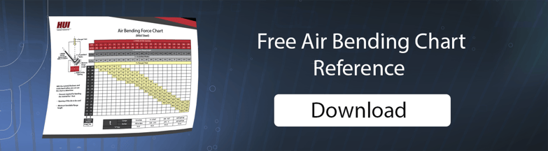
We often receive drawings with different bend radiuses for the same part, or we get radiuses that we don’t have tooling for, so we have to go back and change all the radiuses to make them work. This can take up a lot of time, so using a standard table like the “Air Bending Force Chart” to determine your radius can save both you and your manufacturer a lot of time.
Dimension for ease of manufacturing.
We have some customers who struggle to predict how the sheet metal forming process will affect certain features and dimensions on their parts. You’ll want to reference our blog on dimensioning and dimensioning to formed view to get a better understanding of how to avoid these errors.
Add in “similar to” notes.
Some customers add in “similar to” notes on the bottom of their drawing, which allows our engineers to reference another part that we already manufactured for them. This consistency helps our engineers quickly create work instructions for those new parts.
Additional Tip to Consider
Give your manufacturer access to a private database/webpage of your technical drawings and CAD models.
Make a webpage or database, giving your manufacturer access to every drawing they’ll need. When they will have all the information they need, you should only get questions regarding issues with manufacturability.
Standard work instructions help us create consistency and quality for all of our customers’ industrial parts flowing through HUI. Providing our engineers with a technical drawing including standard bend radiuses, correct dimensions, and “similar to” notes can increase your manufacturer’s efficiency and help your industrial product maintain its projected lead time.
 HUI dedicates itself to helping our customers design the solutions they need and launching quality products on time and within budget.